Engineering in Focus: In Conversation with Jaimie Whitehead

Behind the cloak-like unitised aluminium façade of the new Fisher & Paykel Appliances HQ is a diagrid structure that pushes boundaries of what mass timber can do. We caught up with Jaimie Whitehead, Associate at Dunning Thornton, who worked closely with RTA Studio on the design of this structure.

Both perimeters are a continuous lattice of LVL braces set at roughly 2:1, with no perimeter columns. Under gravity the braces lean against one another and the lattice behaves as a large truss.

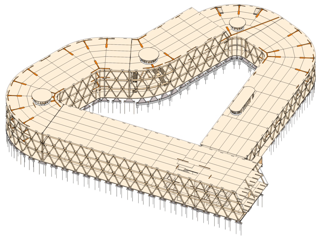
From a distance, the Home building at Fisher & Paykel Appliance’s new HQ reads as a single gesture: a three-storey ribbon of some 260 metres long if you stretch it, which curls around a central pond. Get a little closer, however, and the structure starts to reveal another layer of complexity — one that reflects an innovative spirit and a close collaboration between architecture and engineering.

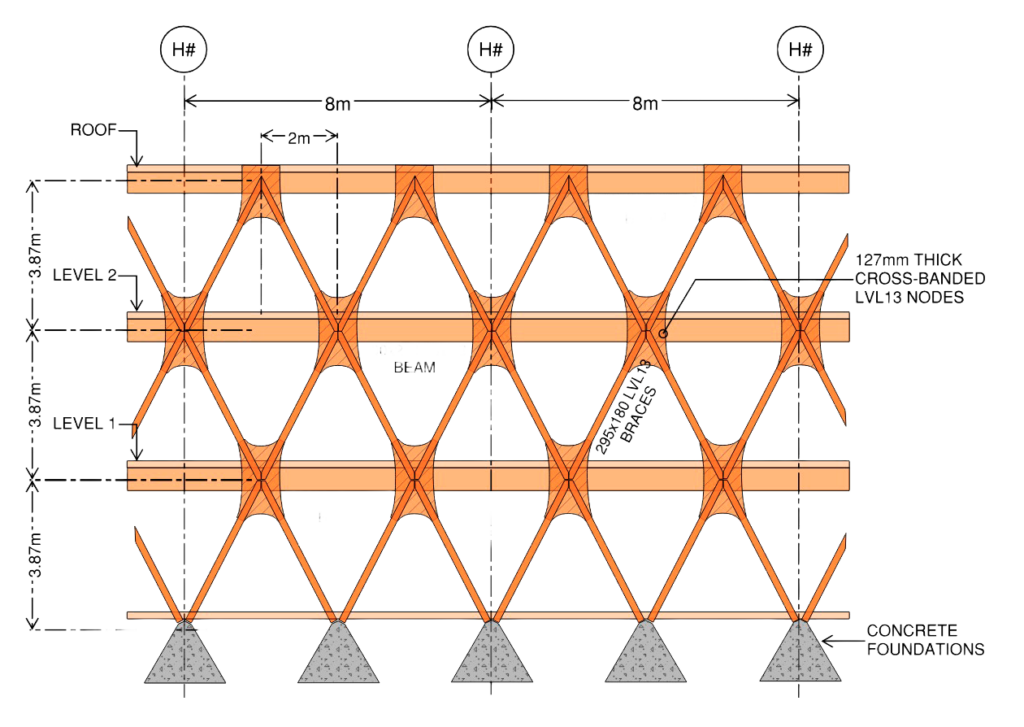
Both the inner and outer perimeters are a mass-timber diagrid, a continuous lattice of laminated veneer lumber (LVL) braces set at roughly 2:1, which carries the floors and resists earthquake and wind. Like the best diagrid structures (think London’s Gherkin or New York’s Hearst Tower) there are no perimeter columns. Under gravity, the braces lean against one another and the lattice behaves as a large truss; under lateral load, it acts as a long run of braced frames. Inside, cross-laminated timber floors span onto LVL beams and a single line of central columns, creating open eight-metre-square bays.

The mass-timber system here got its first run at Scion, the Rotorua innovation hub on which the same architect, alongside Irving Smith Architects and the same engineer, collaborated, but the Home is seven to eight times larger, and it curves, at some points quite dramatically. That combination demanded meticulousness and some serious testing. 

Before any BIM model was opened, the two practices traded hand-drawn ‘fat pen’ mark-ups to agree a set of rules: every curve shares one radius, every beam is the same length node to node, the brace angle never changes, and the diagrid holds a four-metre module around corners as well as along straights. The resulting geometry, with connection angles specified to four significant figures, was then generated with custom Dynamo scripts so that small errors could not accumulate along the ribbon’s length.

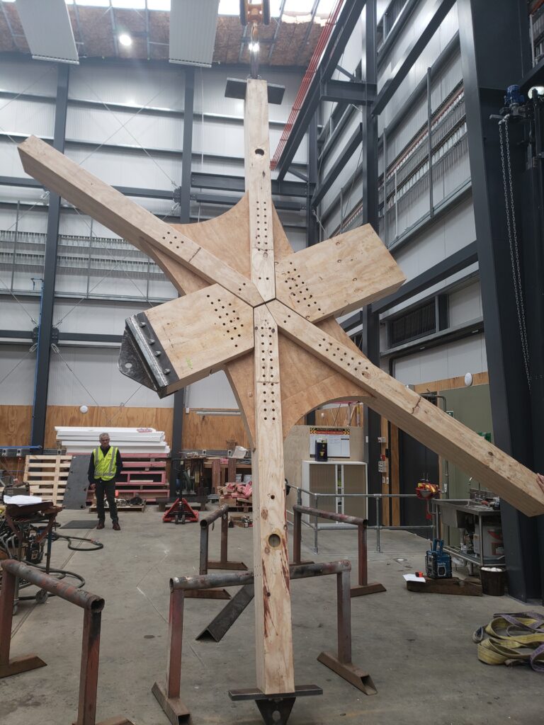
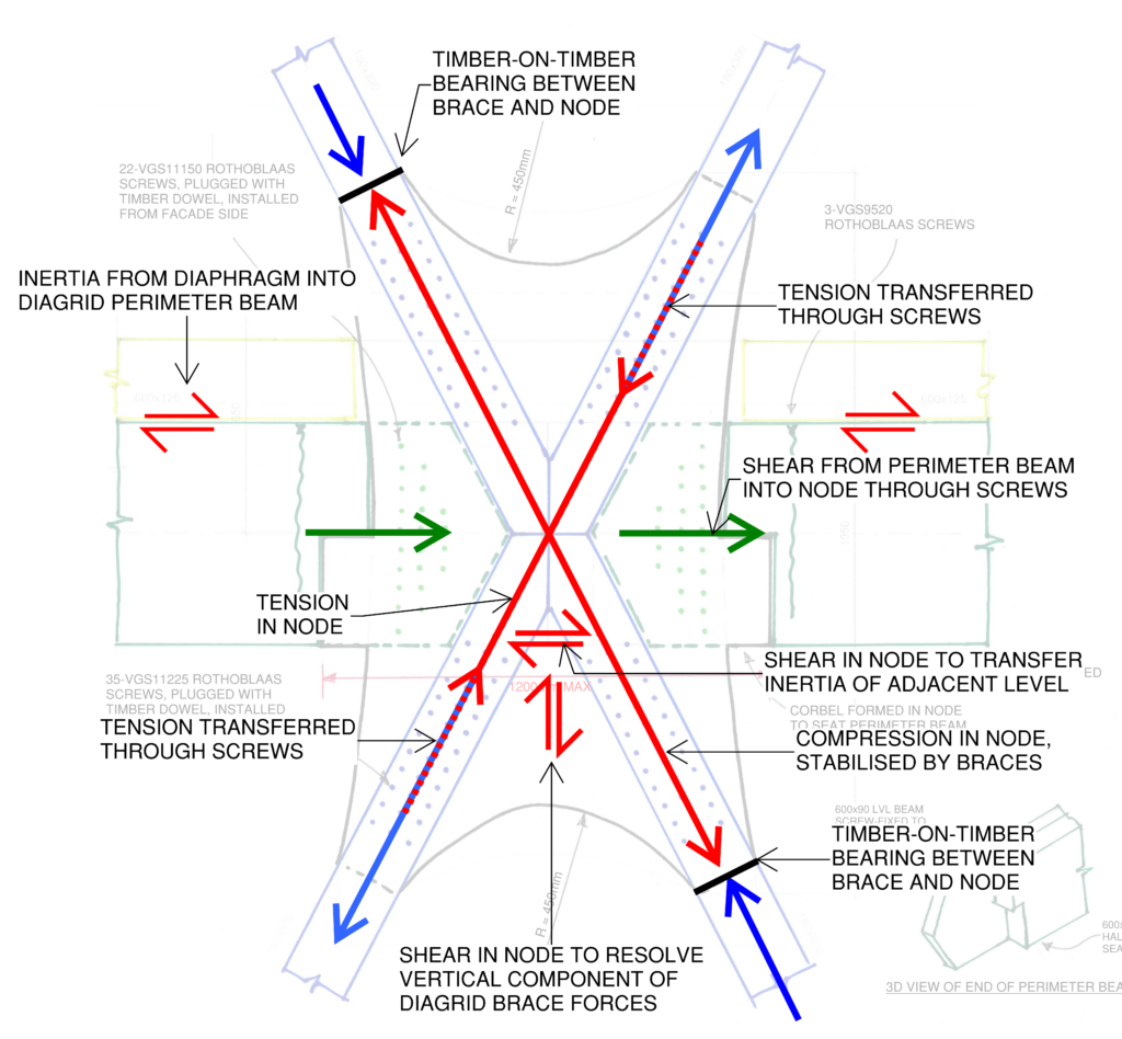
The crux of the design is the node where the braces meet. Rather than Scion’s steel energy-dissipating plates, each of the building’s 337 nodes is a shield-shaped piece of cross-banded LVL onto which braces and beams slot, fixed with fully threaded screws. Those screws are the building’s seismic fuse, designed to yield in a major earthquake so the rest of the structure is protected. The detail was resolved before the analysis model was even built.

Full-scale prototype testing at BRANZ in Wellington revealed a failure that the new national timber standard does not anticipate: the brace splitting along its row of screws. Reinforcing screws solved the problem, and the finding has implications for timber design well beyond this project. 

The 260-metre ribbon is split into four independent structures and set out on an eight-metre grid, with the diagrid on a consistent four-metre module that holds around the curves. A gently pinched, 16-metre-wide ribbon rather than a circle, which helps with orientation. It curls around the Oasis, with the Shed at its northern junction

Architecture Aotearoa: Diagrids are nothing new, but mass-timber ones are; what are its most significant benefits and, from an engineering perspective, biggest challenges? Also, why opt for such a complex system when a less difficult one would have done the trick?

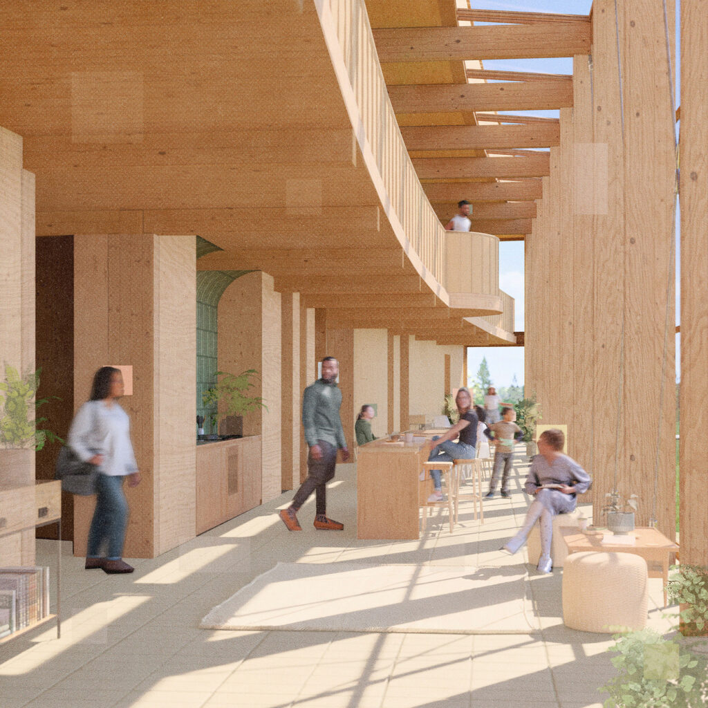
Jaimie Whitehead: The diagrid was part of the client-brief inspired by Scion, as this building showed the structural form was both efficient and visually striking.  The Home was centred on structural-architectural integration, where the diagrid is integral to the finished space. The challenge was to make this efficient by using the diagrid in as many ways as possible. 

Fisher & Paykel challenged us to think about the diagrid through a product-design lens; with design iteration, development and prototyping. We created a ‘kit-of-parts’ to turn something quite complex into a modular solution. Modular design presented opportunities for prefabrication and repeatability, which was critical to achieve efficient design and construction.

The Home grew out of Scion in Rotorua; what did you take from that project, and what had to be rethought once the building became seven or eight times larger and began to curve?

Scion taught us a lot. The node was the hardest part, with the largest forces transferring through it, so we knew to start with the node for the Home. Scion was a diamond-based system, with pre-manufactured kites that used quite labour-intensive techniques to make the bespoke node connections. This worked well for Scion’s smaller footprint but wasn’t feasible for the scale of Home. The curves also required us to rethink the diamond form, so we looked at the diagrid as a component ‘stick’ system to get the diagrid braces to wrap around the curve, rather than facet.

A full-scale prototype of the shield node. Testing at BRANZ in Wellington

Early on, you and RTA Studio agreed on a set of geometric rules: one radius for every curve, identical beam lengths, a constant brace angle; how were those rules negotiated, and where did the architectural ambition and the structural logic pull in different directions?

It was a very collaborative process, and RTA Studio was welcoming of the structural requirements leading the form. We iterated through various module options with hand sketches and then used parametric modelling of the diagrid to show that our hand calculations were accurate. The diagrid modules were continuous along the whole length of the building, so playing with this geometry actually changed the height and shape of the building and its relationship to the site. Parametric modelling allowed us to quickly and accurately iterate and test this with RTA. We then provided our model to the contractor to check the geometry of the shop drawing model.

The main structural-architectural negotiation was achieving the consistent angle of the diagrid braces across the levels, while maintaining the floor-to-floor heights required. This was solved creatively by pushing the ground floor ‘down’ so that the diagrid intersected higher on this level than the upper floors. This maximised the height while still fitting the building between the flood plane and the strict height limits.

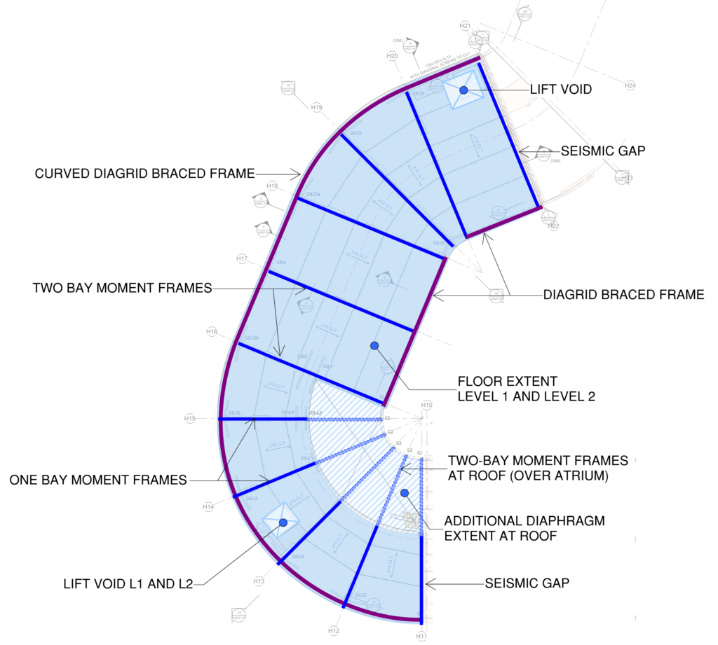
Structural plan of a curved end. The curved ends do much of the bracing, allowing more flexible frames across the floor plate and a more open interior, but they place heavy demands on the floor diaphragms

You exchanged hand-drawn mark-ups with the architects for some time before anyone opened Revit; what does sketching allow that a digital model doesn’t, particularly at the start of a project like this?

I love pen and paper — I think it lets me be more creative. Sketching gets us to think about concepts at a more holistic level, without getting stuck in the millimetres and degrees of precise modelling. We could swap ideas with RTA Studio quickly, which made for a really collaborative workshopping process. 

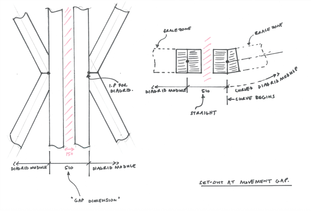
The organic shape of the node was complicated to model, but easy to draw. We calculated the critical dimensions of the node for strength, and then free-handed the curve between these points. The final node shape was essentially traced over a hand sketch, which has given the diagrid form a natural flow that just looks right.

The node was designed before the analysis model existed; why work in that order, and, beyond carrying load, what else did that single detail have to satisfy: fire, fabrication, appearance, the curves?

Timber building design should always start at the connections. Timber can be a brittle material, which on its own doesn’t perform well in an earthquake. Structural engineers address this by adding a ‘fuse’ that can move and dissipate energy during an earthquake. As we learnt from Scion, the node was the critical component of the diagrid design as this would do all this seismic work.

There were a few more things to think about than earthquakes, though.

The detailing of the node needed to consider the loss of timber in a fire (char), as the diagrid supports the floors. Steel heats up in a fire, and that can accelerate the char of the timber, so the screw heads were rebated and plugged with wooden dowels to protect these, and the thickness of the timber in critical locations was checked. The detailing at the node for fire is the governing condition for the size of most of the brace members.

Detailing for fabrication and installation is essential for timber as well. We had to think about how the braces would slot over the nodes on site, particularly the sloped braces around the curves. Making this buildable led to the angled cuts in the braces and the corners of the nodes, which relied on the accuracy of modern CNC technology to get right. 

The diagrid relies on timber-to-timber bearing, which is difficult to add tolerance to while maintaining the diagrid angles and structural load path. It was decided early on that the diagrid braces and nodes would be detailed with minimal tolerance, but that generous tolerances would be detailed in the beams running parallel — essentially the diagrid would be what it would be, and the rest of the building would shrink and stretch to accommodate that.

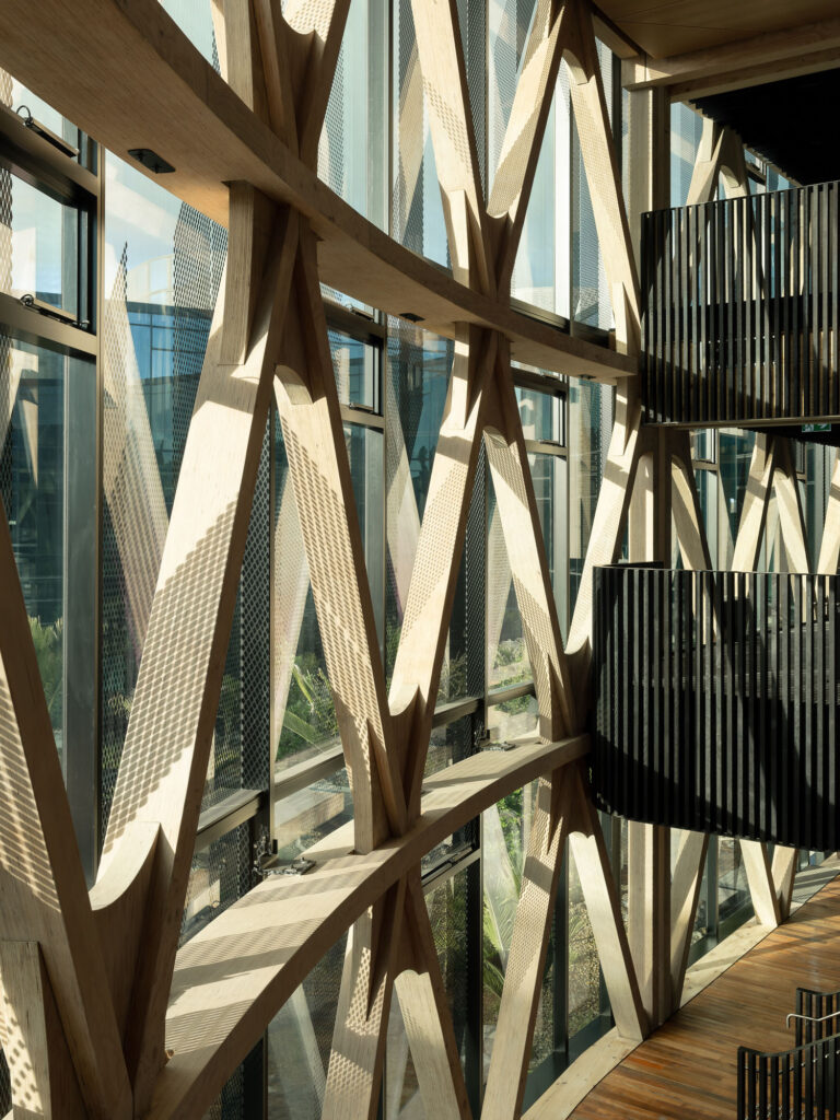
Braces and beams slot over crossbanded LVL nodes on the four-metre module, rising from the concrete foundations. Because every curve is identical, the building needs only three node types: straight, curved and the junction between

You chose screws rather than steel plates as the building’s seismic fuse; what did that decision make possible?

With the project in Auckland (with a lower seismic risk than in many other parts of New Zealand), we didn’t need as much earthquake energy absorption as Scion, so this gave us the opportunity to come up with a different solution for Home. The screwed node was also the lowest carbon option when this was compared at concept stage, which was central to the project brief.

Engineered wood screws are a more modern detailing approach to mass timber than bolts and plates. The screwed connection was simpler to fabricate as it maintained timber-to-timber interfaces, using CNC technology to cut the braces and nodes to millimetre accuracy, and then install the screws. This made the super-low tolerance philosophy for the diagrid feasible.

Each connection has a different number of screws (between 6 and 24 per brace), as we could tailor the design to suit the specific location. This incremental detailing possibly saved thousands of fasteners.

The screws also led to a simpler fire rating approach than steel, which would need to be encapsulated with fire-rated board, which would result in more exposed timber.

The first prototype test split in a way the standard didn’t predict. What was that moment like for the team, what did it change in the building, and what should other designers take from it?

The node had performed quite well up until the split occurred, and it had actually surpassed the force capacity that we had calculated, but the splitting was not a reliable structural behaviour. The splitting wasn’t entirely unexpected, and international standards are now being revised to include this behaviour that has been seen in other testing.

New Zealand has a wealth of timber knowledge, and we were lucky enough to work with PTL as our structural peer reviewers. They were particularly interested in the testing, and we discussed the splitting at length with them to come up with a strategy to reinforce against the splits in an economic way (as there were so many braces to be reinforced).

The prototype process was very valuable for both technical learnings and practical buildability. Technically, it highlighted the importance of good timber detailing, with screw reinforcement. But this was also a great opportunity for the site and design team to come together to test a lot of different things — appearance, scale, tolerances, screw installation — and we made several tweaks to the final design after this process. Prototyping of critical or complex joints is very valuable to a design process, especially if there’s over 300 of them. This comes back to the product-design lens that we started with — if you’re making a lot of something, test it. 

Force paths through the node. Compression passes by timber-on-timber bearing, while tension and shear are carried by the fully threaded screws, designed to yield first in a major earthquake

At his recent Gold Medal lecture, Rich Naish mentioned how the curved ends of the building were particularly difficult to get right; why and how did that engineering complexity shape the plan?

The curves were complex for both global building behaviour and local detailing.

Starting with the detail: when forming a curve, a diagrid brace is not vertical or true to plan. The braces notch over the node, so this cut is on a very precise angle. The beams are then rebated into the node at a different but also very precise angle. We worked with RTA to solve the curved geometry so that every curve was the same, and in the end there are only three node ‘types’ — straight, curved, and the straight-curve interface.

In the bigger picture, the curved ends of the diagrid provided much of the bracing to the building, so this allowed us to use more flexible movement-resisting frames across the floor plate to maximise the openness of the space. The challenge, though, was that the curved sections of the diagrid put a lot of stress on the floor diaphragms. Large steel plates with diagonal screws were used to stiffly transfer these loads, which are discreetly hidden under the non-combustible acoustic raised floor.

At the entry atrium, the curve itself is put to structural work, allowing a 16-metre glazed span with a relatively slender transom so the diagrid can be expressed. Can you describe how that came about, and whether it is a good example of engineering serving the architecture?

In grid-shell structures (Waitomo Glowworm Caves Visitor Centre, for example), the curving of the members creates the strength and stiffness like an arch. This form inspired us to use the curve of the diagrid to provide additional support to the transom. Keeping the transom as minimal as possible maintained the proportions of the diagrid. This is definitely a good example of engineering responding to the architecture, where introducing a small amount of design complexity in our approach changed how the diagrid feels in the space.

A hand sketch of the node. Its critical dimensions were calculated for strength, and the curves between them drawn freehand

What is needed for mass-timber diagrid structures to become affordable and usable in slightly more humble projects than this one; is it policy, know-how among a wider number of architects and builders, or something else?

The mass-timber diagrid is a high-performance structural solution for medium to high-rise buildings. Not every building needs this, but, as we want to push timber higher, there will be more need for this type of structure.

As engineers, we have a role and responsibility for sustainable design and tackling the climate change crisis. Not every building needs to be a mass-timber diagrid to get started in timber; a little bit of timber is better than no timber, bringing sustainability into every project not just a few mass-timber projects.

Any other ‘holy grail’ discoveries, technologies, solutions that you feel would make mass timber more accepted and used globally?

Mass timber can be done at scale, especially with engineered wood products making wood comparable to steel and concrete, plus the advancements in CNC technology. The precision of cutting timber with CNC machines gives closer tolerances, with more opportunity for timber-to-timber detailing. 

The rhythm and repetition of Home meant that prefabrication could be part of its success, which showed the opportunities for a modular approach. It doesn’t need to be rectangular, but it does need the right thinking at the start of a project.

Images: Courtesy of Dunning Thornton

This article originally appeared in Architecture Aotearoa Issue 03. 

Latest video features

In the Coromandel, a home with a humble profile and a thoughtful design makes the most of a stunning location.

Built with awe-inspiring attention to detail, this Arrowtown home is a fresh interpretation of a familiar Otago rural vernacular.

This sculptural Northland bach is a perfect north arrow on a remote farm high above the sea.

With the sun on its bow and the community at its stern, this is a house in which the elements are always front of mind.

Trending articles